EMF vs. Voltage
Electromotive force (EMF) and voltage are two important concepts in Power Engineering, especially in direct current (DC) circuits. This material is briefly touched on in 4th class, but is expanded upon in 3rd and 2nd. Understanding the difference between these two concepts and the relationship between them is crucial. The purpose of this blog post is to provide a guide to EMF and voltage in DC circuits and explain the importance of understanding these concepts.
What is Electromotive Force (EMF)?
Electromotive force, or EMF, is a measure of the electrical energy that drives the current in a circuit. It is the force that causes the flow of electric charge in a circuit. In electrical engineering, EMF is represented by the symbol “E”.
EMF can come from a variety of sources, including batteries, generators, and solar cells. In a DC circuit, the EMF drives the flow of electric charge from the negative terminal of a source (such as a battery) to the positive terminal.
What is Voltage?
Voltage, also known as electric potential difference, is the difference in electric potential energy between two points in a circuit. It is represented by the symbol “V”.
Voltage can be thought of as the electrical “pressure” that drives the flow of electric charge in a circuit. The higher the voltage, the greater the electrical pressure and the faster the electric charge will flow.
EMF and Voltage in Direct Current Circuits
In a DC circuit, the relationship between EMF and voltage is crucial. EMF is the source of the electrical energy that drives the flow of electric charge in the circuit, while voltage is the measure of the electrical pressure that drives that flow.
The relationship between EMF and voltage can be represented by Ohm’s Law, which states that the current in a circuit is directly proportional to the voltage and inversely proportional to the resistance.
Understanding the relationship between EMF and voltage in DC circuits is important for anyone working with electrical devices and circuits. Knowing how these concepts interact can help you to make better-informed decisions about electrical design and troubleshooting.

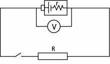
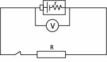
When the switch is in the off position (circuit is open), the voltmeter measures the electromotive force (EMF) in the circuit.

When the switch is in the on position (circuit is closed), the voltmeter measures the potential difference (Voltage) in the circuit.
Formulas
Where:
EMF = Electromotive Force (V)
V = Potential Difference/Voltage in the circuit (V)
I = Current (Amps)
R = Resistance in the circuit (Ω)
r = Internal resistance of a power source (Ω)
If you are presented with a question stating a DC power source voltage, but are not provided with internal resistance of the cell/source, then you can assume this is accounting for an “ideal” battery (no internal loss). In this case, use the voltage as EMF. If you are provided with more information to solve between voltage and EMF, then you should use the above calculations accordingly.

