Power Engineer with 15+ years of experience in pulp and paper, power generation, and oil & gas processing facilities. Operating Manager at Power Engineering 101, helping students prepare for Canadian power engineering certification exams.
Throughout your Power Engineering career you may be required to complete ASME code calculations involving cylindrical components in which you need to know how to determine the maximum allowable working pressure of tubing. The tubing you may be required to determine the maximum allowable working pressure of could be of but not limited to superheater tubes or water tube boiler tubes.
All referenced page numbers are from the 2007 ASME Boiler & Pressure Vessel Code.
Formula
To determine the maximum allowable working pressure of tubing you will use a formula contained within ASME Boiler & Pressure Vessel Code PG-27 Cylindrical Components Under Internal Pressure. Specifically, PG-27.2.1 on page 8
PG-27.2.1 Tubing- Up to and including 5in. (125mm) outside diameter. It is important to remember this point as any piece of material in cylinder shape with an outside diameter bigger then 125mm is now considered to be piping and the equation provided in PG-27.2.2 page 10 must be used.
Formula to calculate the maximum allowable working pressure is:
![]()
Formula Variables
The symbols used within the PG-27 formulas are contained within paragraph PG-27.3 page 10 and are defined as follows:
C = Minimum allowance for threading and structural stability (mm) (PG-27.4, note 3) page 11
D = Or O.D. is Outside diameter of cylinder (mm) “In this case tubing”
E = Efficiency of longitudinal welded joints or of ligaments between openings, whichever is lower (the values allowed for E are listed in PG-27.4, note 1) page 11
e = Thickness factor for expanded tube ends (mm) (see PG-27.4, note 4) page 11
P = Maximum allowable working pressure “Gauge Pressure” (MPa) (see PG-21, refers to gauge pressure)
R = Inside radius of cylinder (mm) “In this case tubing”
S = Maximum allowable stress value at the operating temperature of the metal (Section II, Part D, Table 1A. See PG-27.4, note 2) page 11. It is important when determining the maximum allowable stress value to check (PG-6 plate materials) page 4 and (PG-9 boiler tube materials) page 5 before starting calculations as this information will determine the correct stress table to use by indicating whether the material is carbon steel or an alloy steel.
t = minimum required thickness (mm) (see PG-27.4, note 7) page 12
y = temperature coefficient (see PG-27.4, note 6) page 11
[table id=1 /]
How to: Determine the Maximum Allowable Working Pressure of tubing Questions
Note: All code questions are to be calculated in (mm) and (MPa) unless otherwise stated. Convert accordingly and properly before the calculation.
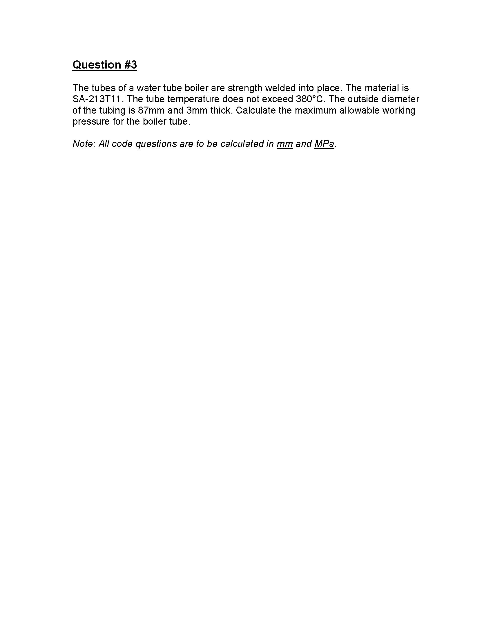
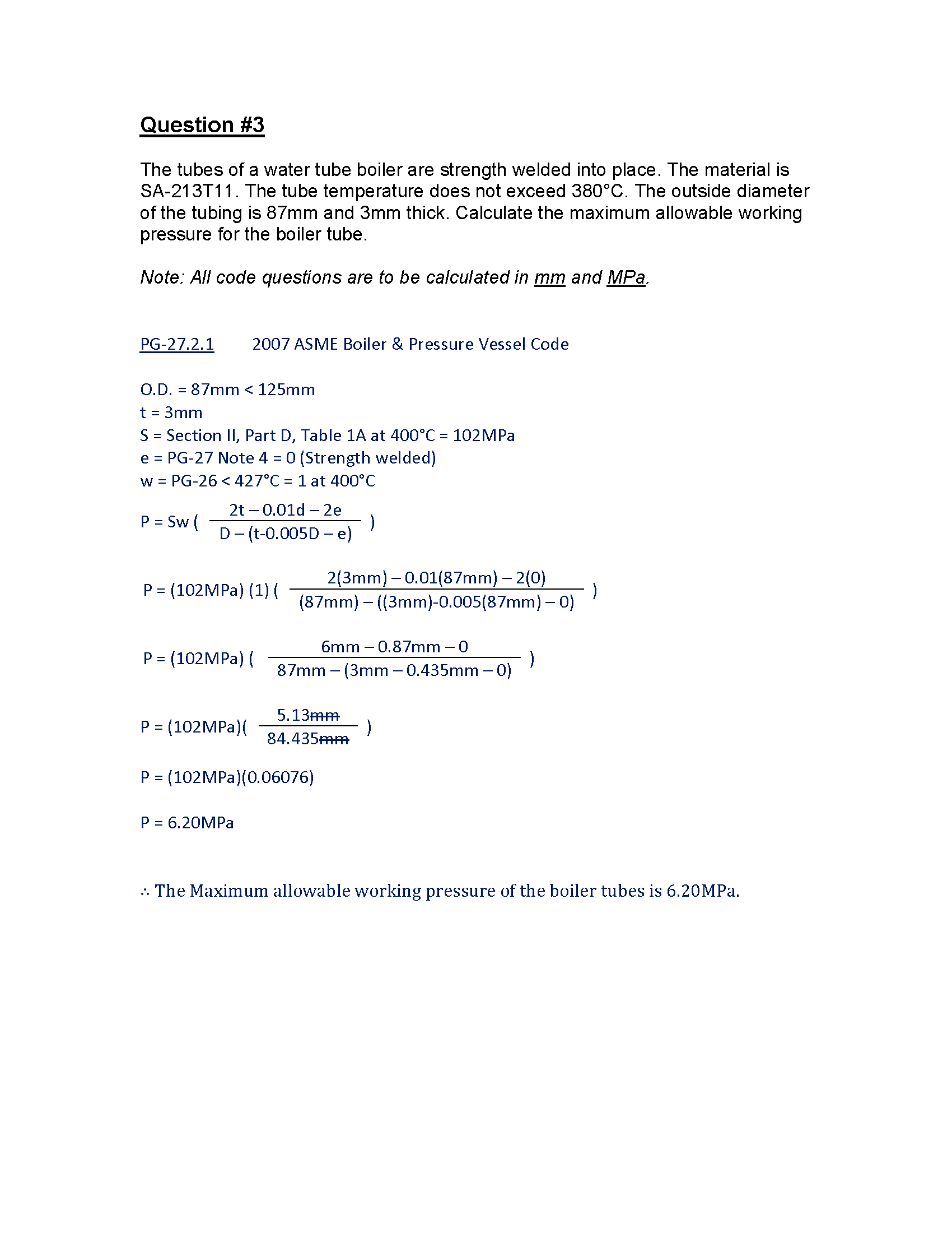
Question #3
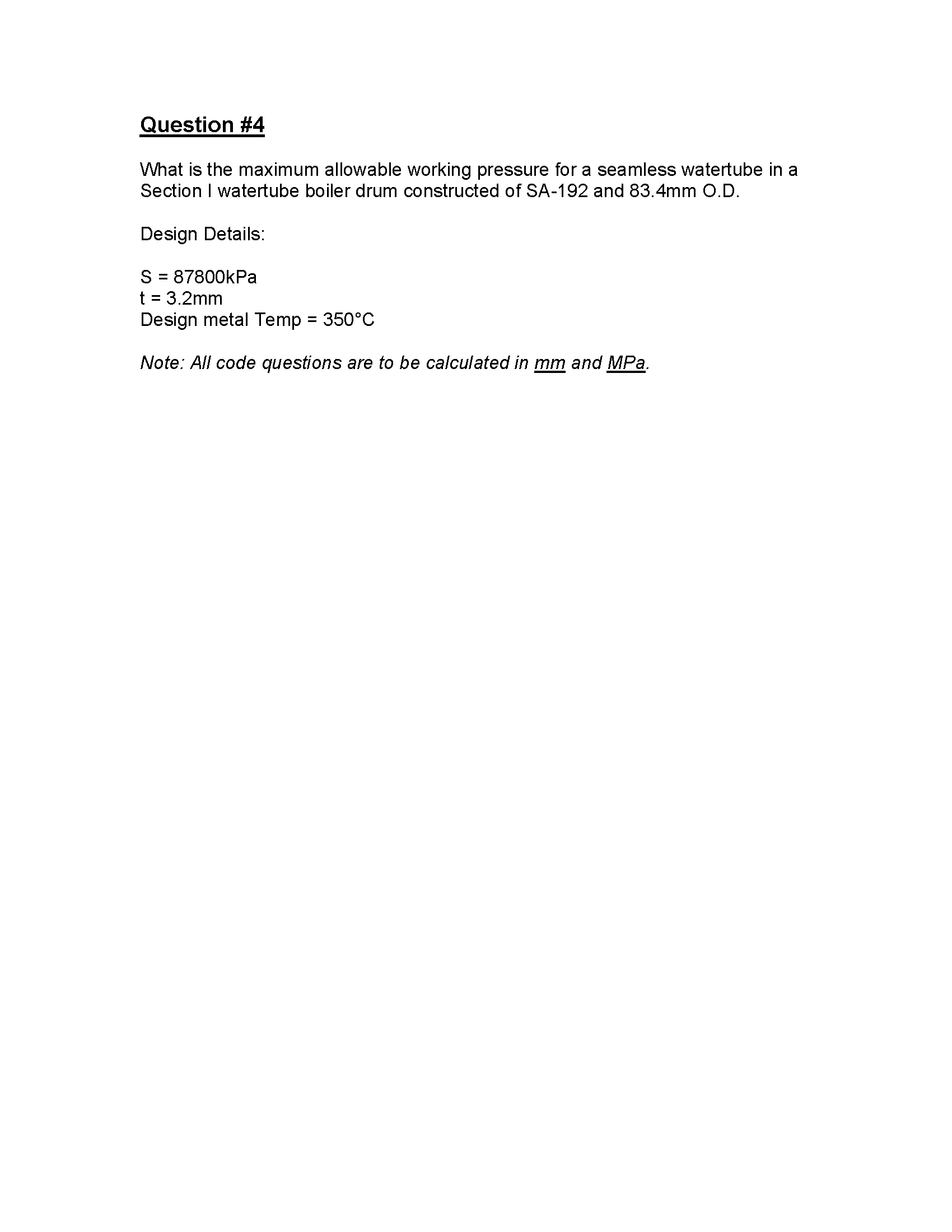
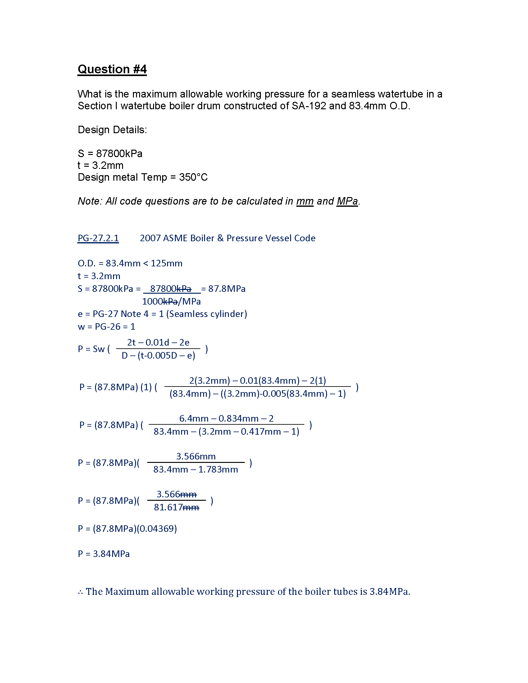
Question #4
Determine The Maximum Allowable Working Pressure Of Tubing Summary
I hope the examples provided help you understand how to calculate the maximum allowable working pressure for tubing. Let me know your thoughts in the comments below.
Thank you,
Power Engineering 101