Power Engineer with 15+ years of experience in pulp and paper, power generation, and oil & gas processing facilities. Operating Manager at Power Engineering 101, helping students prepare for Canadian power engineering certification exams.
Today we will be reviewing calculations involving how to the minimum required thickness of circular unstayed flat heads and covers. We will review the formula(s) to determine the required thickness and the maximum allowable working pressure. Then define the different variables in each of the formulas and review a couple practice questions to reinforce the material covered.
All referenced page numbers are from the 2007 ASME Boiler & Pressure Vessel Code
Formula
PG-31.3.2 page 15 The minimum required thickness of flat unstayed cicular heads, covers, and blind flanges shall be calculated by the following equation:
Minimum Required Thickness Formula

The minimum required thickness formula above can be transposed to determine the maximum allowable working pressure of flat unstayed circular heads, covers, and blind flanges.
Maximum Allowable Working Pressure Formula
![]()
The above formula is not provided in the 2007 ASME Boiler & Pressure Vessel Code
Formula Variables
The variables used in the formulas provided above to determine the minimum required thickness of circular unstayed flat heads and covers are defined in PG-31.2 page 15 as follows:
C = A factor depending on the method of attachment of head and on the shell, pipe, or header dimensions, and other items listed in PG-31.4 below, dimensionless. The factors for welded covers also include a factor of 0.667 that effectively increases the allowable stress for such construction to 1.5S.
d = Diameter, or short span, measured as indicated in Fig. PG-31
m = the ratio tr/ts, dimensionless
P = Maximum allowable working pressure
S = Maximum allowable stress value, psi (kPa), using values given in Table 1A of Sections II, Part D
t = Minimum required thickness of flat head or cover
tr = Thickness required for pressure of seamless shell, pipe, or header.
ts = Minimum specified thickness of shell, pipe, or header.
[table id=1 /]
How To: Determine The Minimum Required Thickness Of Circular Unstayed Flat Heads And Covers Questions
Note: All code questions are to be calculated in (mm) and (MPa) unless otherwise stated. Convert accordingly and properly before the calculation.
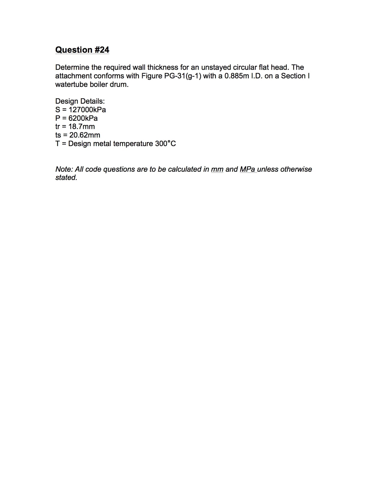
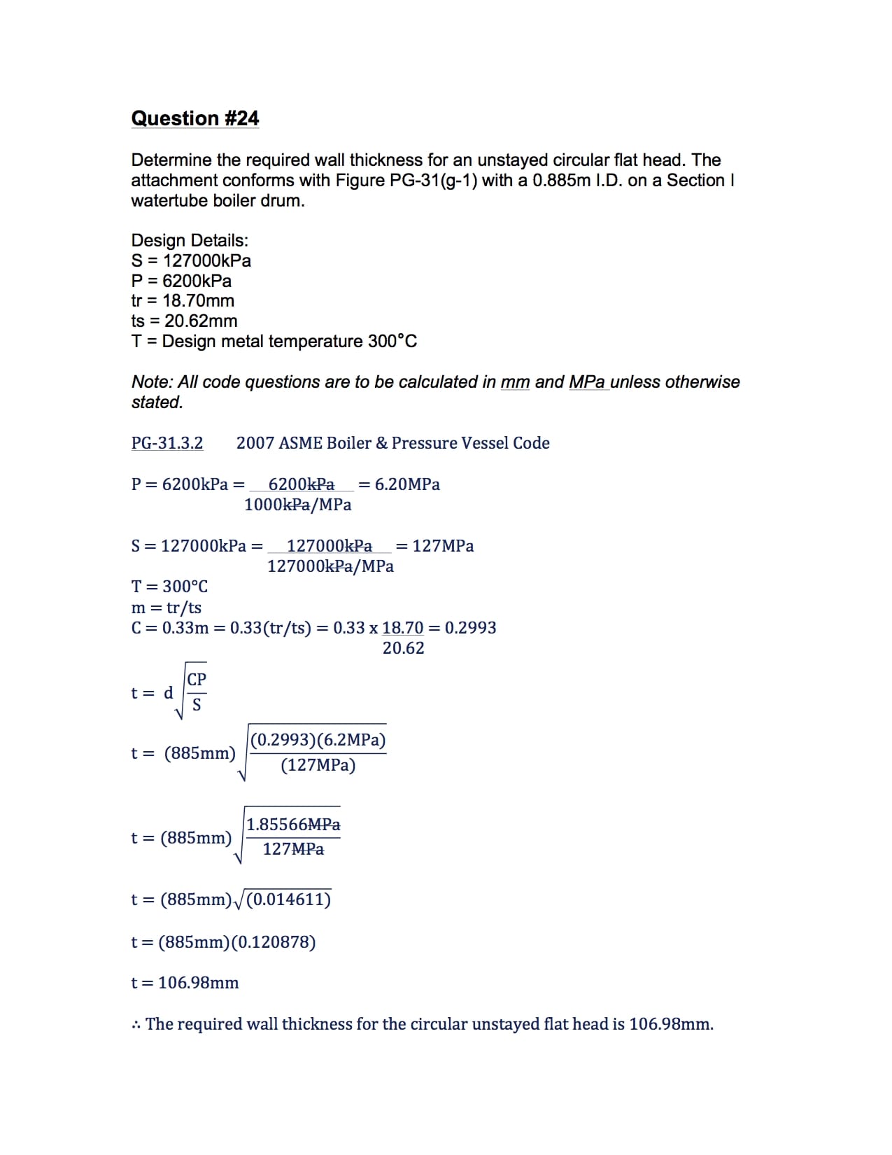
Question #24
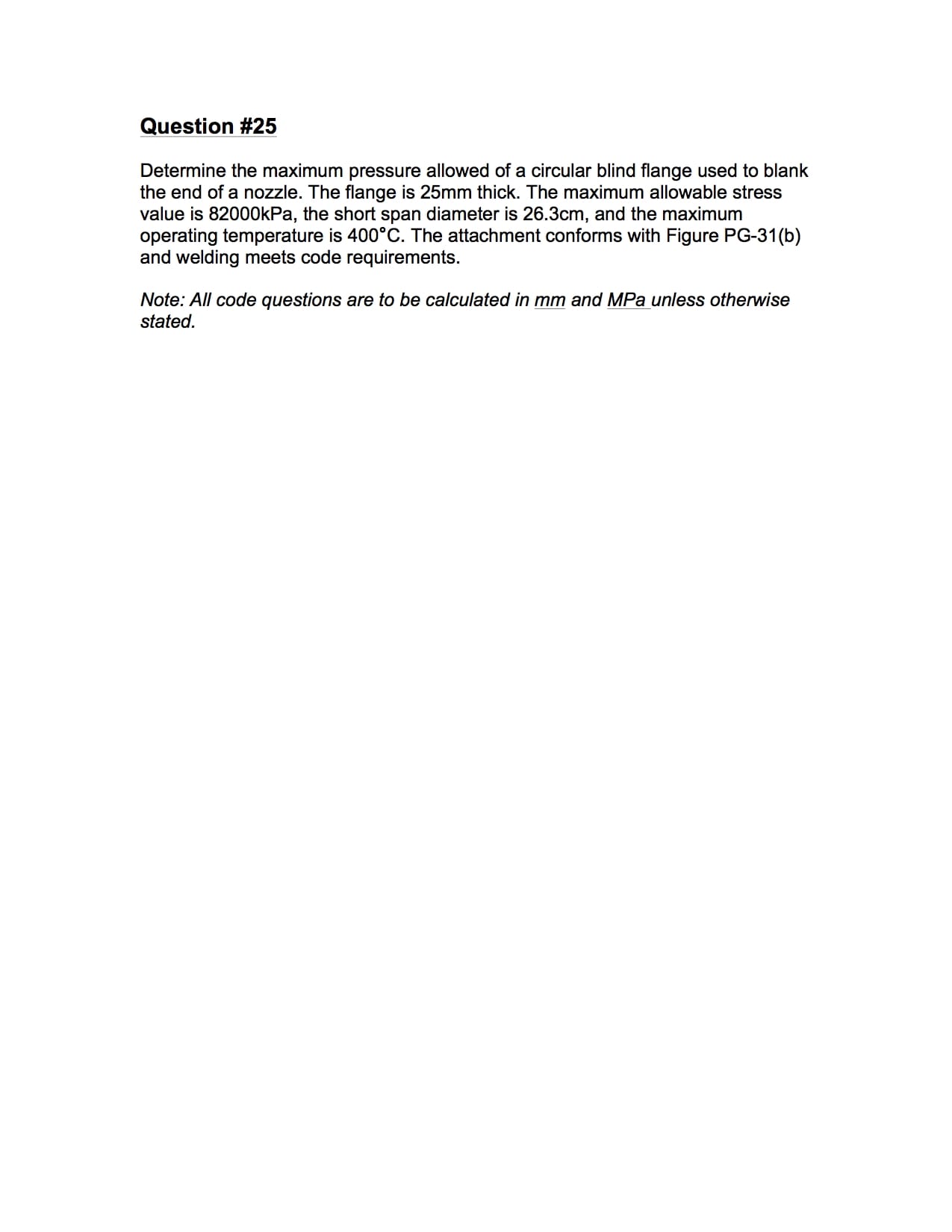
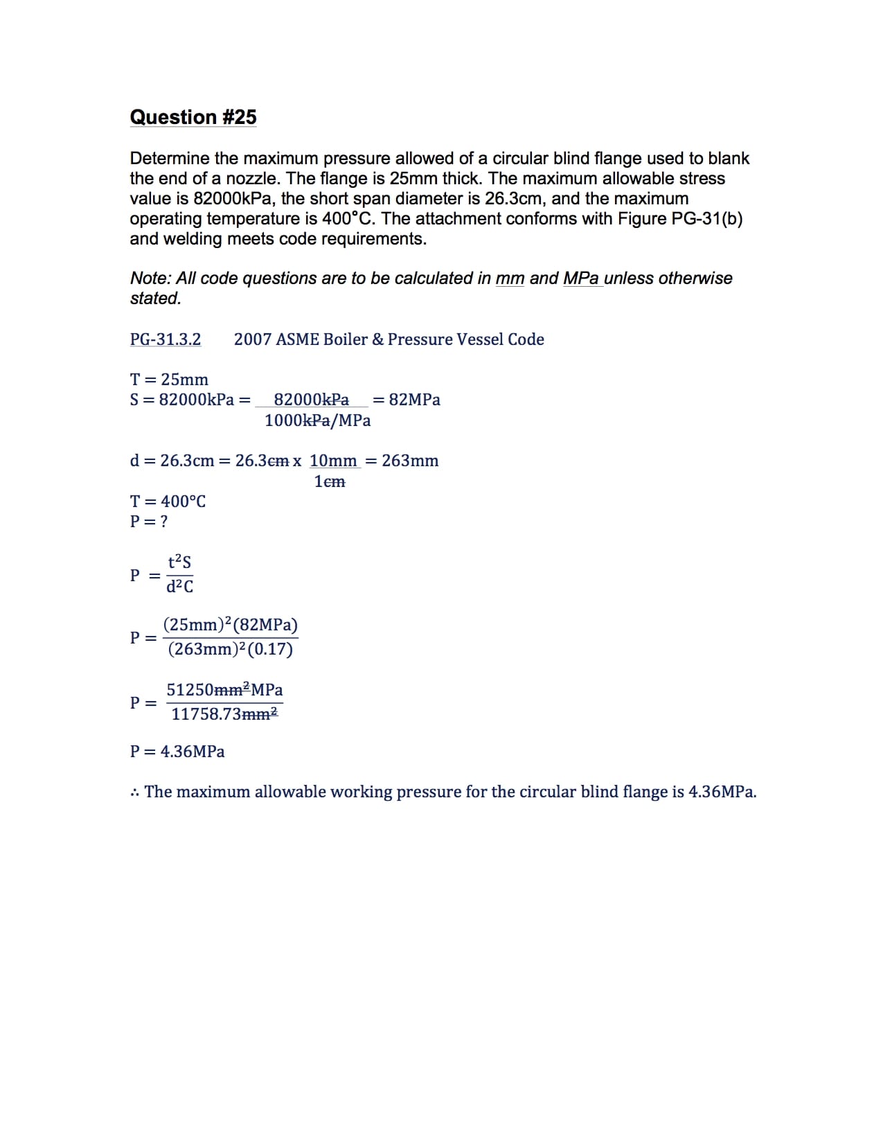
Question #25
Summary
Remember that the above formula is only to be used when determining the required thickness or maximum allowable working pressure of circular unstayed flat heads, blind flanges, and cover questions. In question #24 the attachment conformed to PG-31(g-1) which tells you to “See Note (1)”. Note (1) can be found at the bottom of the page under NOTES: page 18.
Thank you everyone,
Power Engineering 101